An IBM 7090 digital computer and Stromberg-Carlson 4020 Microfilm Printer have been used to produce a series of interesting and novel patterns. This paper describes the mathematical and programming techniques used but neglects any discussion of the artistic merits of the results.
The digital computer is presently being used to produce new musical sounds and techniques of composing. The advent of microfilm printing used in conjunction with a digital computer allows similar excursions into the field of visual art. Thus, it would certainly be interesting to attempt the creation of novel designs by using the IBM 7090 computer and the Stromberg-Carlson 4020 Microfilm Printer. This paper describes the results of such an exploratory series of design-producing experiments.
Rather than risk an unintentional debate at this time on whether the computer-produced designs are truly art or not, the results of the machine's endeavors will simply be called Patterns.
The subroutine package for the SC-4020 Microfilm Printer includes a subroutine that draws a series of straight lines connecting successive points of some previously-specified array. Another subroutine simply plots dots at the points specified. Since these two subroutines were used to create all the patterns, the medium is obviously limited to combinations of straight lines and dots.
To produce a pattern, it is first necessary to formulate a means of determining the array of points. The array actually consists of pairs of x-axis and y-axis coordinates listed in the order in which they are to be plotted. Either of the two microfilm subroutines mentioned previously can then be used to produce a pattern from the array.
A versatile tool in producing the arrays of coordinate points is a subroutine called WNG (White Noise Generator). This subroutine calculates an array of random numbers of any specified standard deviation. By choosing a large standard deviation, it is possible to obtain a point outside the range of the plot. When this occurs the point is reduced modulo the maximum size of the plot until it falls within the proper range. This technique seems to add more randomness and interest to the patterns.
The following paragraphs explain briefly the schemes used to produce each pattern.
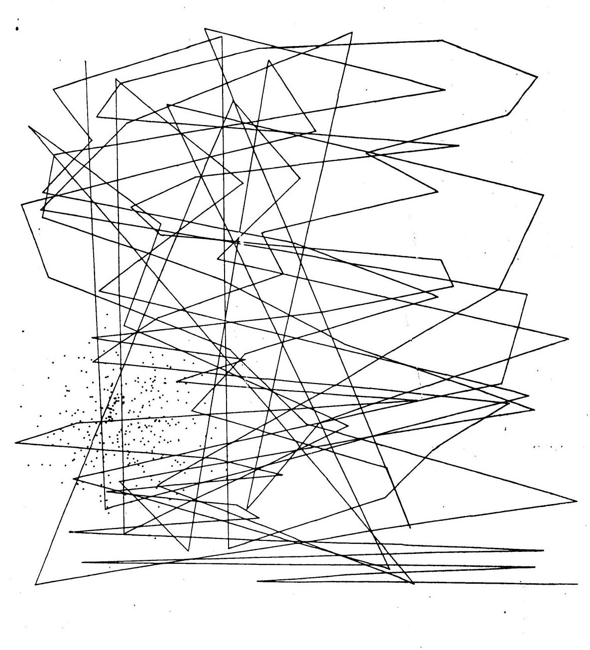
Pattern One. The straight lines in Pattern One were created by connecting a series of points. Random numbers (standard deviation of 1200) were used for the x-axis coordinates while the y-axis coordinates were produced from a quadratic equation with consecutive integers as the variable. The scattering of faint dots on the lower left portion of the pattern was produced by random x-axis and y-axis coordinates (standard deviation of 75) about the point (200, 300).
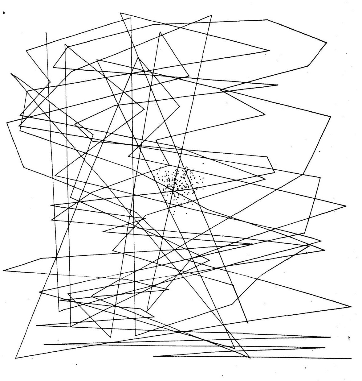
Pattern Two. The straight lines in Pattern Two are exactly the same as those in Pattern One. However, more dots have been added, and they have been made somewhat darker. The FORTRAN program used to create this pattern is explained in the Appendix.
Pattern Three. Pattern Threeis another variation on the basic straight lines of Pattern One and Pattern Two. This time the dots have been moved to the exact center of the drawing with a smaller standard deviation of 30.
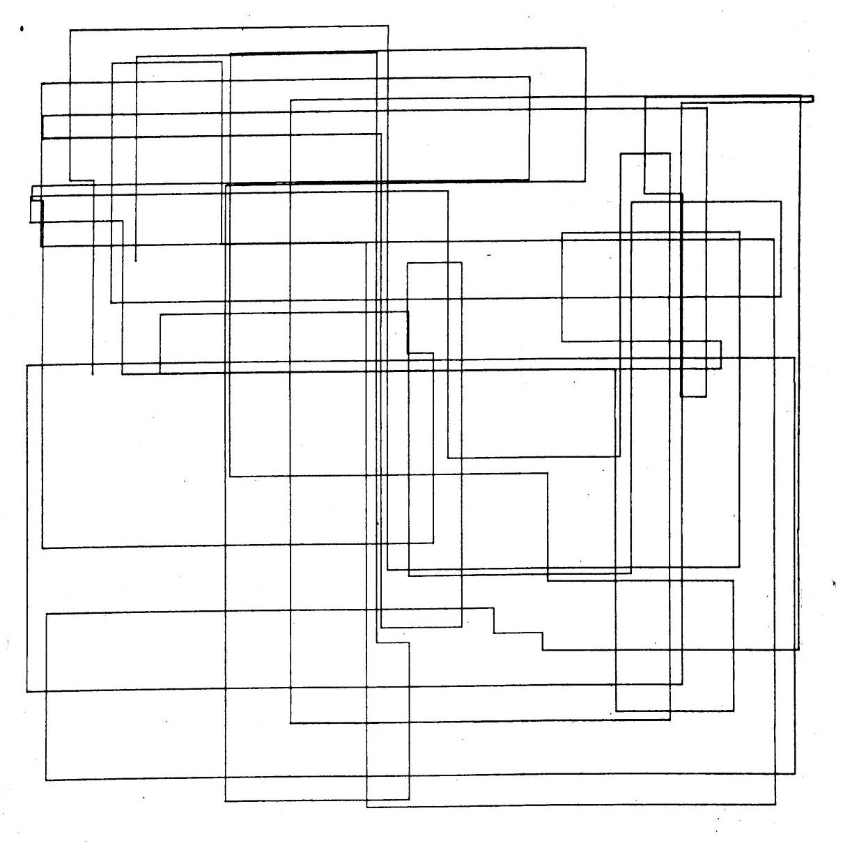
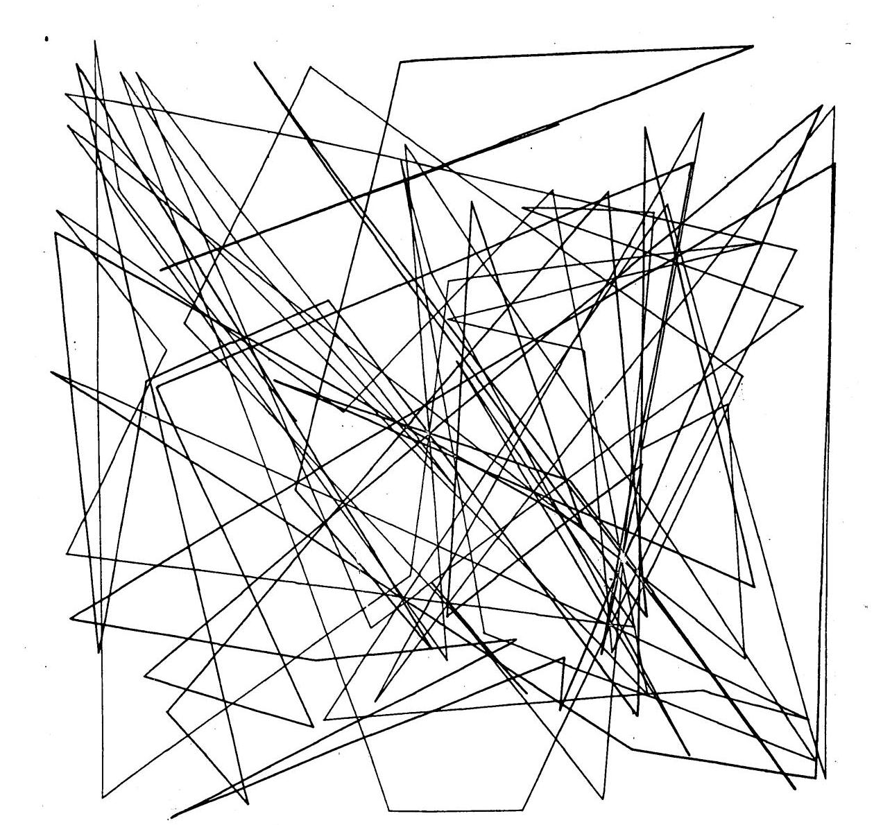
Pattern Four. A connected series of straight vertical and horizontal lines forms the structure of Pattern Four. The points specifying the lines were produced from random arrays (standard deviations of 3200 and 2000 for the x-axis and y-axis coordinates respectively). The valuesof x- and y-coordinates were alternately repeated to make the lines vertical and horizontal.
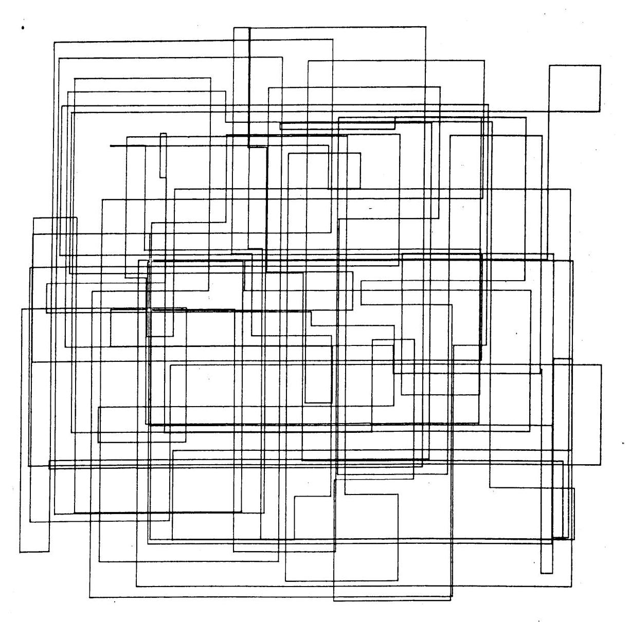
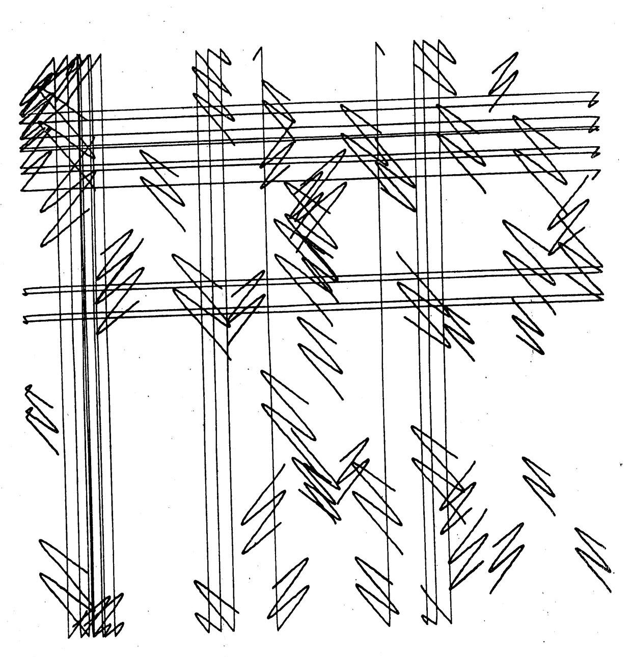
Pattern Five Pattern Five is a variation of the preceding pattern except that more lines were plotted and the standard deviations were changed to 2500 and 4000 for the x-axis and y-axis coordinates respectively.
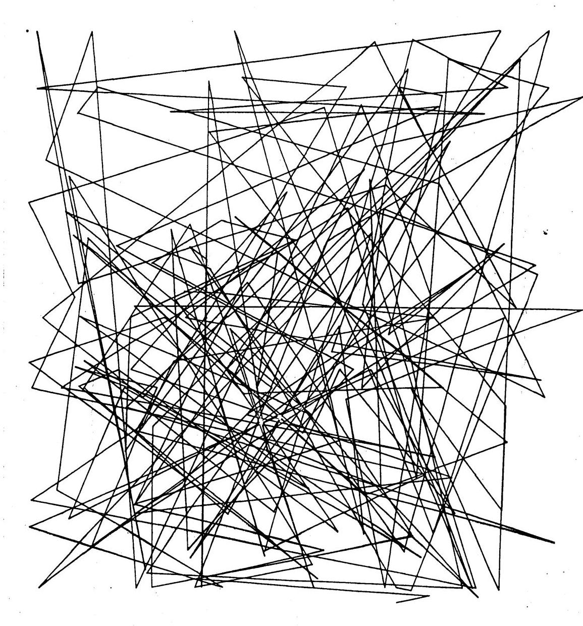
Pattern Six. Random numbers were used for both the x-axis and y-axis coordinates (standard deviations of 3200 and 2000 respectively) of the points connected by straight lines in Pattern Six.
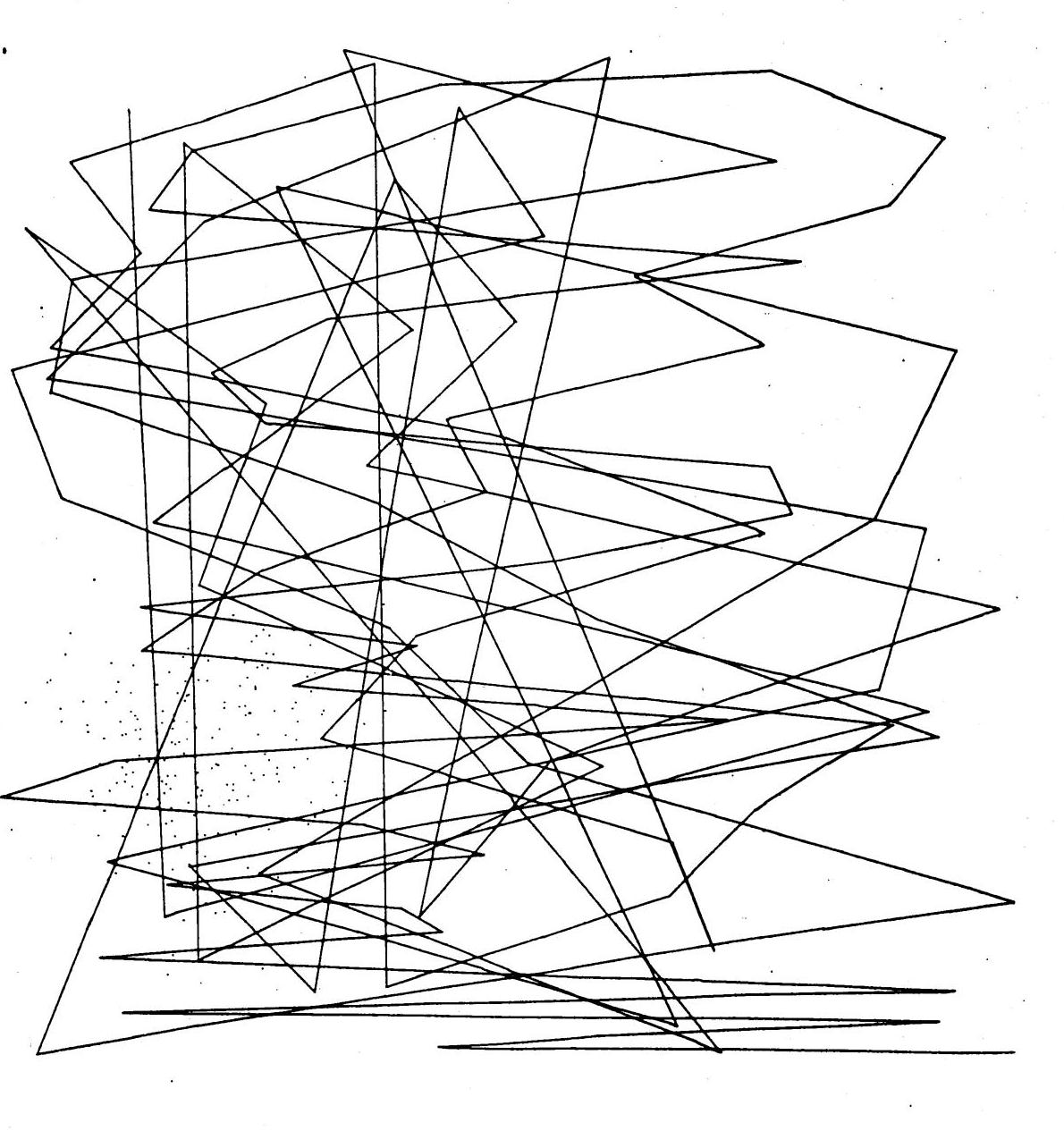
Pattern Seven. Pattern Seven was supposed to have been a series of randomly-placed prolate cycloids but apparently something went amiss.
Pattern Eight. The straight lines in Pattern Eight connect points whose x-axis coordinates are random numbers (standard deviation of 2000) and whose y-axis coordinates were computed by a cubic equation.
The series of variations on Pattern One were produced by varying only the number, position, and darkness of the dots. The straight lines in the first three patterns are exactly the same but minor changes in the dots make them seem different. The prominence of certain combinations of the lines seems to be determined by the position of the dots which apparently focuses the observer's attention.
The programming schemes used to produce the patterns shown in this paper were obviously conceived without forethought for their artistic merit. A more interesting procedure would be first to study the various pattern producing capabilities of the 7090 and associated microfilm equipment. Next some subjective experiments might be attempted to try to determine just what qualities make a picture pleasing or even artistic. With this information at hand, the programmer-artist mightrue art.
A listing of the FORTRAN program used to produce Pattern Two is shown at the end of this Appendix. When using the microfilm subroutines, it is first necessary to advance the film with the instruction CALL ROLL. CALL REFPT assigns the coordinate (0,1023) to upper left hand corner of the frame. The maximum lengths of the top and side are 1024 and are specified in the CALL REFPT argument.
After initializing the microfilm printer, the arrays of points to be plotted are determined. The DO 100 loop calculates a table of y-axis coordinates by a quadratic equation and stores them in the array IY1. The first CALL WNG creates a table of 200 random numbers with standard deviation 1200 and stores the table in the array FX1. The arrays FX2 and FY2 are similarly created by the WNG subroutine. The DO 101 and DO 102 loops fix these arrays.
The next step is to plot lines joining the computed points or to simply plot them as dots with the proper microfilm subroutines. The DVR2 subroutine draws 98 lines from (IX1(1), IY1(1)) to (IX1(2),IY1(2)), (IX1(2), IY1(2)) to (IX1(3),IY1(3)), etc.
TSP1 puts the boolean character specified at location B (here a dot) on the 299 points whose coordinates are given in the arrays IX2 and IY2. The subroutine is called four times to make the dots darker. CALL CLEAN ends the plotting and CALL SYSTEM ends the program.
C PATTERN TWO
      DIMENSION FX1(300),IX1(300),IY1(300), FX2(300),FY2(300),IX2(300),IY2
     1(300)
B     B=526060606060
      CALL ROLL
      CALL REFPT(0,1023,1024,1024)
      DO 100 I=1,200
 100  IY1(I)=I*(I+5)
      CALL WNG(FX1,200,1200.)
      CALL WNG(FX2,300,75.)
      CALL WNG(FY2,300,75.)
      DO 101 II=1,200
 101  IX1(I)=FX1(I)
      DO 102 J=1,300
      IX2(J)=FX2(J)+200.
 102  IY2(J)=FY2(J)+300.
      CALL DVR2(IX1,IY1,99)
      CALL TSP1(IX2,IY2,B,299)
      CALL TSP1(IX2,IY2,B,299)
      CALL TSP1(IX2,IY2,B,299)
      CALL TSP1(IX2,IY2,B,299)
      CALL CLEAN
      CALL SYSTEM